Interactive design of aesthetic abstract textures (AAT)
AAT generation program flow
The AAT generation program flow is illustrated below: you select a color palette, an initial AAT model and some basic parameters using sliders. Then you click on the RUN button and you obtain as outcomes the final AAT model, an image with the renderization of the AAT, and another renderization including symmetry.
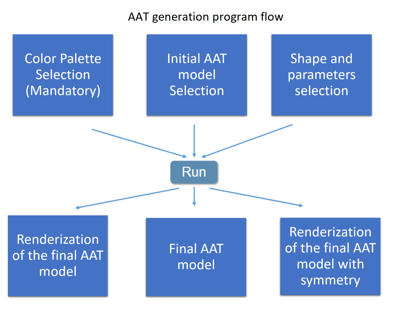 |
The initial AAT model is described by a pretty large collection of parameters that you can edit in an editable text file. Initially you do not need to pay attention to the content of this text file because the AAT model can also be modified in a simplified way using a few number of sliders. When you click on the RUN button the program collect the information of the initial AAT model, the selection on color palette and parameters and generates a new AAT model which is used to render the AAT. This new AAT model is described in a non-editable text file.
We propose an experimental learning model. To get familiar with the interface capabilities, we suggest to the user to select any of the AAT model that we include as examples, modify some of the AAT parameters using the sliders, run the program and see the effect of the parameter selection in the outcomes. At the beginning of the online interface you have access to the demo "Archive" where you can access and reconstruct any experiment performed with the online interface. In the following sections we will explain in more details the different steps of the AAT generation. Once you get familiar with the interface, to make the most of the interface capabilities you need to learn how to modify the AAT model using the editable text file. This is the "expert mode" that we will explain in details in the last section.
Color palette and "Upload data" button
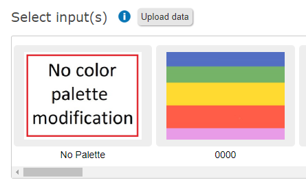
- If you do not want to modify the default palette defined in the current AAT model you select "No color palette modification".
- You can choose a color palette among the proposed ones.
- You can upload your own color palette using the "Upload data" button.
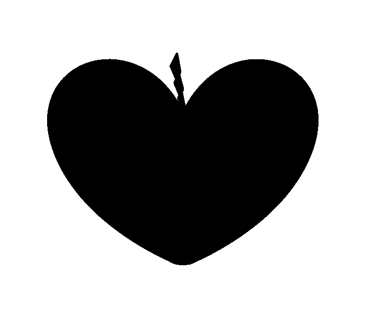
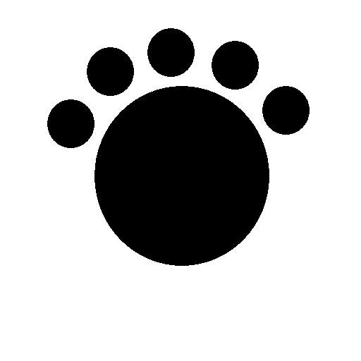
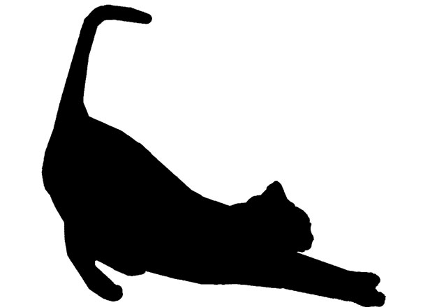
Using the "Upload data" button you can also upload your own basic shapes to generate your AAT. A shape is given by an image containing a black silhouette in a white background. Below you can find two examples of shapes you can test
 |
 |
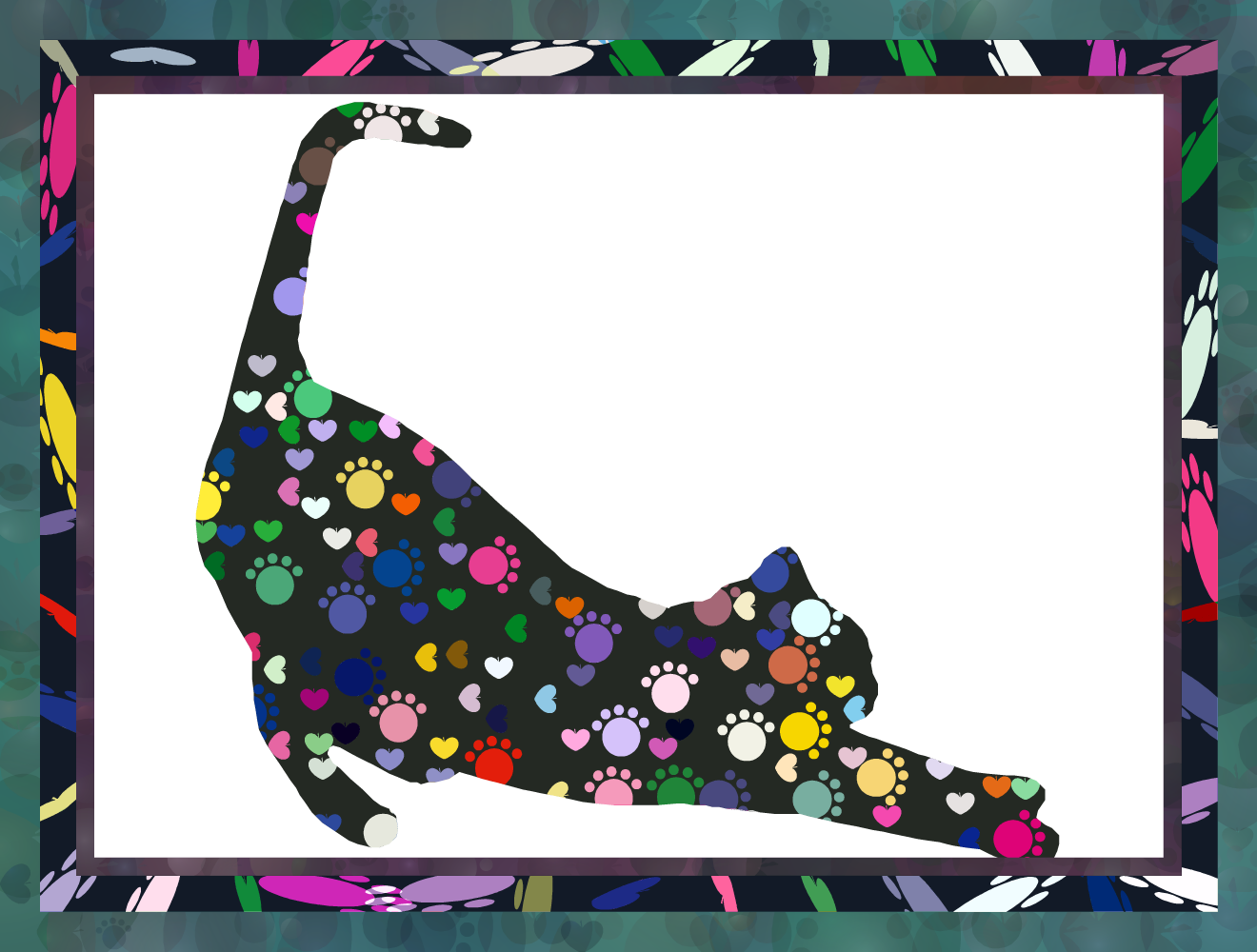
You can upload a single shape (in an image format) or a collection of shapes in a compressed file. Finally, you can upload a silhouette for the background. This option is used when you want to draw the texture inside a given silhouette. In the next figure we show the silhouette of a cat and an AAT texture created using this silhouette as background. To generate the AAT we used the examples of shapes given above.
 |
 |
Selecting an AAT model
 |
 |
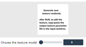
There are three ways to select your initial AAT model:
- You can generate a completely new AAT model using a random generator (position 0 in the associated slider (see fig. above)). In this case, initially, the AAT parameter editable text area is empty and each time you click on the RUN button you generate a new AAT from scratch and the ATT model appears in the output ATT parameter text area. If you like one of the random generated ATT and you want to modify it you have to copy the content of the output text area into the input text area.
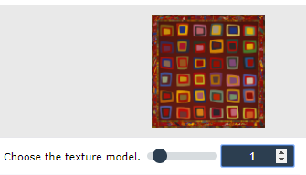
- You can choose an AAT model among the proposed ones (position 1,2,.. in the associated slider (see fig. above)).
- (expert mode) You can copy-paste in the editable text area an ATT model text parameter file that you have previously edited.
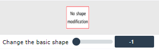
Basic shape selection
 |
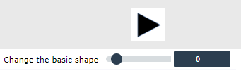 |
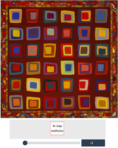
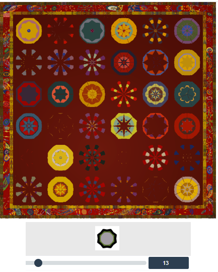
You can edit the basic shapes used to built the AAT by selecting an option in the associated slider (see fig. above) or by uploading your own collection of silhouettes using the "Upload data" button (see above). The default option "No shape modification" means that you use the default value defined in the initial AAT model. When you select a shape with the slider, the AAT generator is going to use the same type of shapes everywhere. In the expert mode we will see that you can combine different shapes in the composition. You can even combine shapes provided by you as silhouettes with the shapes provided in the interface. Below we show a figure to illustrate the results obtained with two different shape selection configurations
 |
 |
Basic modification of the AAT main parameters
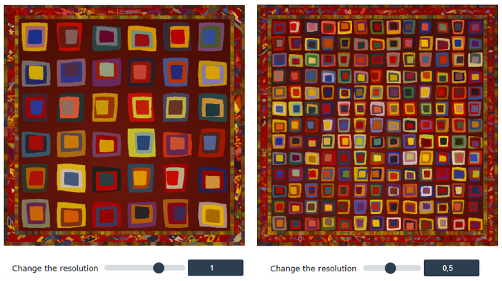
"Change the resolution" slider allows to modify the AAT resolution scale. (the lower the resolution the smaller the shapes)
|
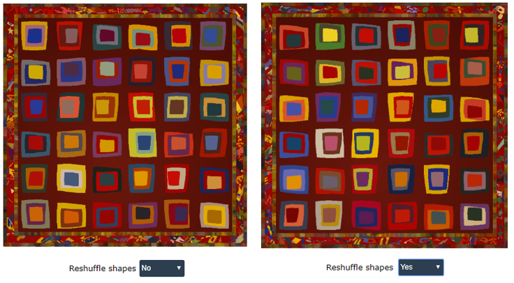
Reshuffle shapes : this option generates a similar AAT changing the random shape positions
 |
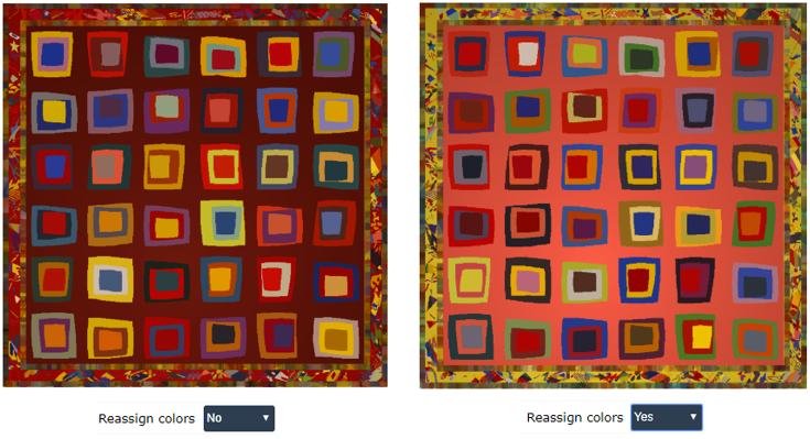
Reassign colors : without changing the palette, the assignment of colors to shapes is randomly modified.
 |
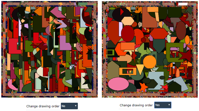
Change drawing order : change the order the shapes are drawn.
 |
Expert mode. Full understanding of the AAT parameters
To make the most of the AAT generator interface you need to understand the AAT model parameters which are editable in the editable text area of the input AAT model. Most of the parameters are understandable by experiment. We invite the user to select one of the proposed AAT models, modify their parameters in the editable text area, click on the RUN button and see the effect of the modification in the outcomes.
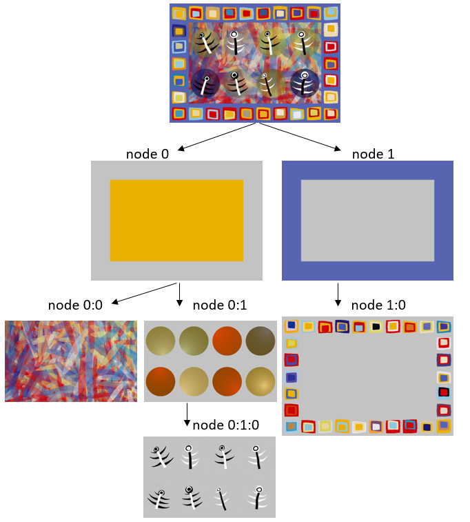
The first thing you have to understand is the tree organization of the AAT parameters. In the figure below you can find an example of such tree organization for a particular AAT model. In this case we can observe that the first level of the tree (nodes 0 and 1) are composed by a central rectangle and one external strip band. The next level of the tree is given by the nodes 0:0 and 0:1 which are children of the node 0 and the node 1:0 which is a child of node 1. Finally in the third level of the tree we have the node 0:1:0 which is a child of the node 0:1. (notice that we use the symbol ':' to indicate in a compact way the node tree level information). The first level of the tree (nodes 0 and 1) do not contain shapes. It just represents an initial subdivision of the AAT. Currently the interface allows an initial subdivision based on a central rectangles an any number of consecutive border stripe bands (the information about such initial subdivision is included in the HEADER of the AAT parameter file. For each one of the rest of nodes (nodes 0:0, 0:1, 1:0 and 0:1:0) we have to define shapes, composition rules and rendering properties used to fill the shapes of the parent node.
 |
The HEADER of the AAT parameter text file
Next we explain in details the parameters (in red) of the HEADER of the AAT parameter text file using as example the AAT of the figure above.
IMAGE ASPECT RATIO = 1.43 (the ratio between the AAT width and height)
NORMALIZED IMAGE HEIGHT = 1 (The normalized image height is always 1. All other length parameters in the image (point coordinates, diameters, thickness, distance) refer to this unit.)
BORDER THICKNESS = 0.160 (thickness of Persian carpet type stripes. They are separated by symbol :, for example 0.02:0.04:0.02). This parameter determines the first level of the data tree organization. The initial subdivision of the AAT image is given by a central rectangle and a number of border stripes fixed by this parameter.
DEFAULT COLOR PALETTE IMAGE = * (an image with the default color palette. It is optional, if the file exists it is used to color all shapes). This parameter is only used when the user upload her/his own color palette image.
BACKGROUND COLOR OF THE CONTAINER RECTANGLE AND THE BORDER STRIPES. To assign RGB background colors is not mandatory. If this information is not filled then the program will assign to the backgrounds random colors
R = 233:86:210:86:80:233 (red channel of the rectangle and stripes separated by symbol :)
G = 177:100:1:100:96:181 (green channel of the rectangle and stripes separated by symbol :)
B = 0:177:6:177:173:11 (blue channel of the rectangle and stripes separated by symbol :)
LIGHT SPOT OF THE CONTAINER RECTANGLE = -1.000 (if nonpositive no light spot effect is applied, otherwise usual value ranges from 0.5 to 8.). Light spot is a render effect where the color intensity is attenuated according to the distance to a light spot center. The larger is the value of this parameter, the stronger the color intensity attenuation.
LIGHT SPOT CENTER x COORDINATE = 1.26
LIGHT SPOT CENTER y COORDINATE = 0.41
HEIGHT OF THE GENERATED IMAGE IN PIXELS = 2048. This parameter determines the height of the AAT image renderization. The width will be fixed according to the IMAGE ASPECT RATIO parameter.
ORDER TO DRAW SHAPES = 0 (if negative shapes are drawn in a random way. Otherwise they are drawn in the order they have been built)
RESOLUTION OF THE TEXTURE = 1.00 (the lower the resolution the smaller the shapes, the default value is 1, it can range from 0.1 to 4.). This parameter is used to change simultaneously the size of the shapes in all nodes.
Node description in the AAT parameter text file
For each child node (0:0, 0:1, 1:0, 0:1:0, etc..) we have to include a description of the composition rules and rendering properties we use for the node. You can freely remove/add nodes configuration using copy-paste of any node configuration of any proposed AAT model. Next we explain in details the node parameters (in red) using as example the node 0:0 of the AAT illustrated in the figure above.
DEPTH OF THE NODE = 0:0 (depth of node index separated by symbol :)
RANDOM SEED = 1688290069 (random seed to initiate random sequence in this node ( = )). By changing the value of this parameter you will obtain a similar AAT but sorting the shapes in a different way.
BASIC SHAPE = 43 This parameter represent the index of the basic shapes used in this node. Using the slider "Change the basic shape" in the online interface you can see the index associated to each shape. The default shape database provided by the program contains 43 shape types. If you have uploaded your own shapes using image silhouettes, then the indexes for these new shapes start in 44. Index 44 means that you will use all shapes you have uploaded, index 45 means the you will use only the first shape you have uploaded, etc.. Notice that for technical reasons, the shapes you upload do not appear as option in the slider "Change the basic shape". You can change the relative size of the different shapes you upload by adding such information to the image filenames you are going to upload. For instance, if you have 2 shapes given by the images named foot.png and apple.png and you want the shape foot.png be twice as the reference size for a shape you can rename the file as foot_z2.png. If you want the shape apple.png be the middle of the reference size for a shape you can rename the file as apple_z0.5.png. In this case when both shapes are used together in a texture, the size of the foots will be 4 times larger than the size of the apples. This parameter also allows a more advanced usage: in the case you want to combine a particular collection of shapes, for instance, circles (shape index 2) stars (shape index 4) and triangles (shape index 0) and you want else that size of the stars be twice larger than the size of circles and the size of triangles be the half of the size of the circles, then you write BASIC SHAPE = 2:1.0:4:2.0:0:0.5
SHAPE DIAMETER = 0.050 (default shape diameter size. The number of shapes to include is computed to cover the father shape using such shape diameter. The smaller the shape diameter, the larger the number of shapes)
SHAPE LOCATION DISTRIBUTION = 1 (0: random, 1: square grid, 2: hexagon grid, 3: Delaunay, 4: shapes centered in stripes of Persian carpets 5: contouring 6: Mondrian type). This parameter determines the way the shapes are distributed in the parent node. Next we show a more detailed description of the options:
- 0: random : the location of the shapes are randomly sorted in the parent shape
- 1: square grid : the location of the shape in the parent shape follows a regular square grid distribution
- 2: hexagon grid : the location of the shape in the parent shape follows a regular hexagon grid distribution
- 3: Delaunay : the shapes are located at the vertex of a Delauny triangulation of the shape
- 4: shapes centered in stripes of Persian carpets : This is an special configuration for the border stripe bands. The shapes are located regularly along the center of the band
- 5: contouring : The shapes are located contouring the boundary of the parent shape. We can contouring inside or outside the shapes and we can also fix the distance of the contouring shape with respect to the boundary of the parent shape. This behavior is controlled with the next 2 node parameters.
- 6: Mondrian type. : The parent shape is filled with Mondrian type rectangles.
- 7: Periodic pattern in stripes of Persian carpets : A random periodic pattern is used to fill the stripes of Persian carpets
MIN CONTOURING DISTANCE = -0.029752 (min distance between the contouring shape and the shape to be contoured, only applies for shape location distribution equals to 5), distance_contouring>0 : contouring outside the object (<0 inside)
MAX CONTOURING DISTANCE = -0.073182 (max distance between the contouring shape and the shape to be contoured, only applies for shape location distribution equals to 5), distance_contouring>0 : contouring outside the object (<0 inside)
The final shapes included in the AAT are built by affine transformations of the basic shapes. We manage the affine transformations using the following decomposition
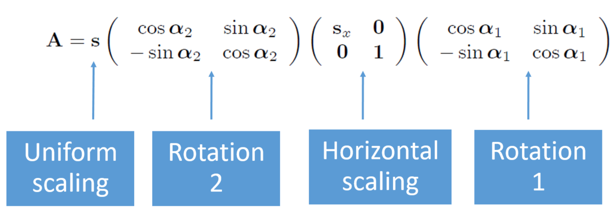 |
ROTATION 1. MIN ANGLE = 0 (affine transformation. min shape rotation angle (in radians))
ROTATION 1. MAX ANGLE = 0 (affine transformation. max shape rotation angle (in radians))
ROTATION 1. NUMBER OF ANGLES = 1 (affine transformation. number of angles to sort for rotation 1)
MIN HORIZONTAL SCALING = 1.0 (affine transformation. min horizontal scaling to apply to the shape)
MAX HORIZONTAL SCALING = 1.0 (affine transformation. max horizontal scaling to apply to the shape)
ROTATION 2. MIN ANGLE = 0 (affine transformation. min shape rotation angle (in radians))
ROTATION 2. MAX ANGLE = 3.141593 (affine transformation. max shape rotation angle (in radians))
ROTATION 2. NUMBER OF ANGLES = 2 (affine transformation. number of angles to sort for rotation 2)
MIN UNIFORM SCALING = 2. (affine transformation. min uniform scaling to apply to the default shape size)
MAX UNIFORM SCALING = 16. (affine transformation. max uniform scaling to apply to the default shape size)
The next 3 parameters deal with the interaction of a shape with the parent or brother shapes
INCLUSION FATHER = -1 (shape interaction. 0: activated, -1: no activated). When activated a shape is inserted only if it is included in the father shape
EXCLUSION BROTHERS IN THE SAME NODE = -1 (shape interaction. 0: activated, -1: no activated). When activated a shape is inserted only if it does not intercepts shapes in the some node
EXCLUSION BROTHERS IN OTHER NODES = -1 (shape interaction. 0: activated, -1: no activated). When activated a shape is inserted only if it does not intercepts shapes in other brother nodes
The next parameters concern the render configuration of the node
RANDOM SEED COLOR = 425945547 (random seed to initiate random sequence when color assignment). Changing this parameter you obtain a different color distribution using the same palette and the same shapes
BORDER THICK = 0.0 (: >0 a black border is delineated in the shape boundary)
PALETTE INDEX = 26 (index of palette in the default palette database ). This parameter represent the color palette to be used. Only applies in the case the user has not uploaded her/his own palette and no tesselation effect is applied. The index number corresponds to the number assigned to the palette in the online interface slider to select the palette.
MIN TRANSPARENCY = 0.400 (value ranges from 0 (opaque) to 1 (full transparency))
MAX TRANSPARENCY = 0.800 (value ranges from 0 (opaque) to 1 (full transparency))
MIN LIGHT SPOT = -1.000 (if nonpositive no light spot effect is applied, otherwise usual value ranges from 0.5 to 8.)
MAX LIGHT SPOT = -1.000 (if nonpositive no light spot effect is applied, otherwise usual value ranges from 0.5 to 8.)
TESSELLATION PALETTE INDEX = -1 (if <0 no tessellation, otherwise it is the palette index to color the shape with tessellation). When activated the image tessellation generated by the object boundaries is used to render the texture “behind” the new drawn shape. Colors are associated independently to each new connected component of the image
KEEP FATHER INCLUSION = 0 (0: shapes are not drawn outside its father, -1: the opposite). When activated, the shapes are not drawn outside their parent shape.